
Industrial Product Design & Development: Complete Engineering Guide from Concept to Mass Production in India
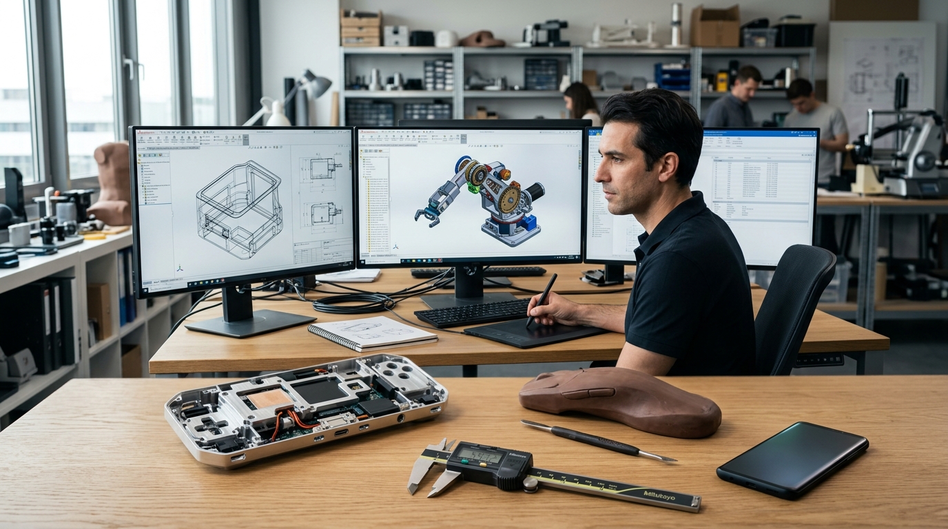
In today's competitive global hardware ecosystem, developing a successful physical product requires far more than aesthetic styling or a preliminary 3D concept. Industrial product design and development (NPD) is the multidisciplinary engineering discipline that translates raw market opportunities and functional requirements into reliable, cost-optimized, and mass-manufacturable hardware. For startups, MSMEs, and Tier-1 automotive and electronic manufacturers in India, mastering this development lifecycle is critical to avoiding expensive tooling re-works and delayed product launches.
At ThinkToReality, our dedicated industrial design and engineering lab in Delhi NCR guides creators through each strategic development phase. From human-centric ergonomics and Class-A surfacing to Design for Manufacturability (DFM) reviews and final production tooling, this comprehensive guide explores the complete industrial design process step-by-step.
Phase 1: Market Research, Product Architecture & Ergonomic Ideation
Every new product starts with a clear functional brief. Industrial designers begin by defining internal component architecture—including PCB dimensions, battery packs, motors, fasteners, and display interfaces. Once the internal hardware packaging is established, designers create thumbnail concept sketches exploring user ergonomics, handheld grip comfort, thermal venting, and brand styling cues.
During this phase, usability considerations take center stage. For medical hardware, handheld power tools, or consumer IoT devices, user interaction points—such as button tactile feel, status LED light pipes, and port accessibility—are mapped out before creating digital CAD models.
Phase 2: Parametric 3D CAD Modeling & Class-A Surfacing
After selecting the winning aesthetic concept sketch, engineers transition into parametric 3D CAD modeling using advanced software suites such as SolidWorks, Siemens NX, and Rhino. Unlike freeform animation meshes, parametric CAD geometry contains precise mathematical curvature, feature history trees, and exact dimensional constraints necessary for CNC machining and injection mold tool cutting.
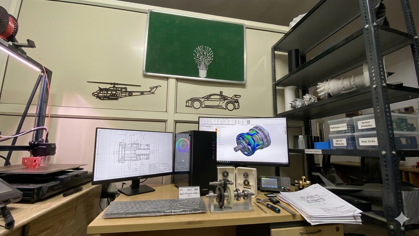
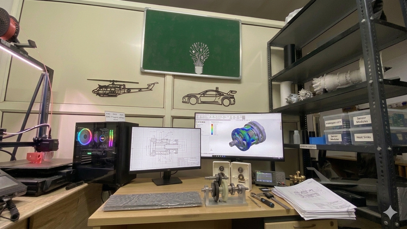
Parametric CAD assembly architecture and internal mechanical gear layout designed by ThinkToReality engineers.
For aesthetic consumer products and vehicle panels, Class-A surfacing techniques ensure smooth, continuous surface transitions (G2 curvature continuity). This eliminates unsightly surface reflections, parting line distortions, and tooling imperfections during plastic injection molding.
Phase 3: Design for Manufacturability (DFM) & Assembly (DFA)
A brilliant 3D CAD model is useless if it cannot be manufactured affordably at volume. Design for Manufacturability (DFM) is the vital bridge between design concepts and factory production. ThinkToReality's engineering team conducts extensive DFM audits to ensure your product can be produced without cosmetic defects, excessive scrap rates, or expensive complex tooling.
Key plastic injection molding DFM parameters include:
Phase 4: Structural FEA Simulation & Stress Analysis
Before committing capital to physical tooling, digital Finite Element Analysis (FEA) simulates mechanical stresses, impact forces, thermal dissipation, and torsional bending loads on the product model. Identifying high-stress concentration zones in software allows engineers to add localized gussets and optimize material usage, reducing part weight while enhancing structural safety factors.
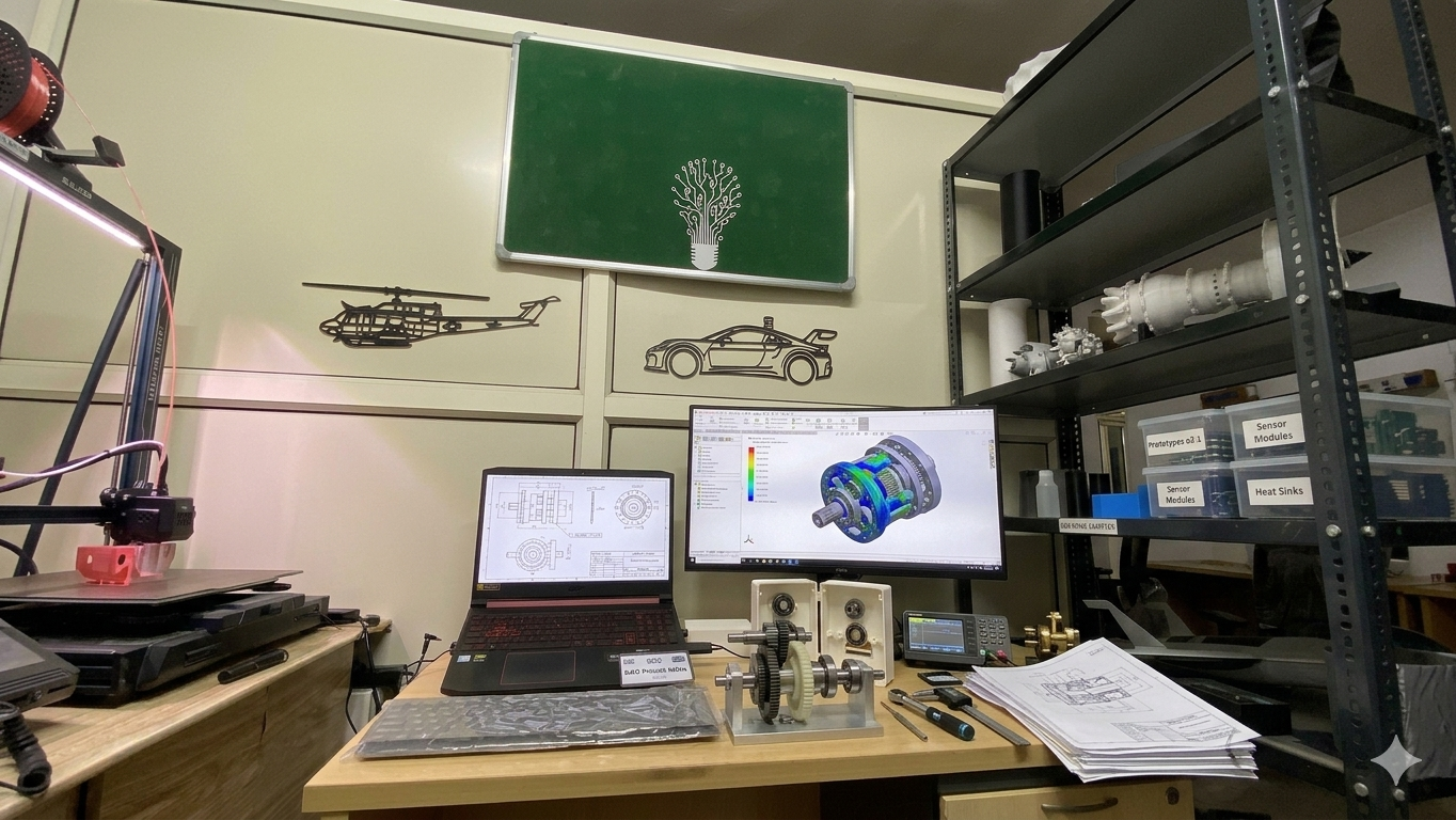
Finite Element Analysis (FEA) stress distribution simulation on a structural chassis at ThinkToReality.
Phase 5: Rapid Functional Prototyping & Field Validation
Physical prototyping is the ultimate design reality check. Using industrial SLA resin printing, SLS nylon sintering, and multi-axis CNC machining, ThinkToReality fabricates functional prototypes within 24 to 48 hours in Delhi NCR. Prototypes allow your engineering team to verify PCB fitment, drop-test enclosures, test waterproof gasket compression (IP55 to IP67), and pitch tangible prototypes to investors and enterprise clients.
Phase 6: Tooling Fabrication & Transitioning to Mass Production
Once physical validation passes all QA benchmarks, ThinkToReality generates 2D AutoCAD manufacturing drawings with complete Geometric Dimensioning and Tolerancing (GD&T) specifications. We then engineer hardened tool steel injection molds (P20, H13) or progressive sheet metal stamping dies, delivering seamless transition from low-volume trial batches (100 to 1,000 units) to full commercial mass manufacturing (10,000+ units).
Summary: Industrial Design Milestones & Typical Timelines
Conclusion: Accelerate Your Product Launch with ThinkToReality
Industrial product design is a high-stakes engineering journey where precision planning saves millions in manufacturing costs. Whether you are building an EV charging station, a medical diagnostic monitor, or a smart consumer IoT device, ThinkToReality provides full-stack product development under one roof. Contact our engineering design team today to turn your napkin sketch into a certified physical reality.
Related Insights
Sheet Metal Design & Precision Fabrication Guide: DFM Guidelines, Bending Tolerances & Manufacturing in India
A definitive engineering guide to precision sheet metal design and custom fabrication in India. Learn essential DFM rules, K-factor & bend deductions, CNC fiber laser cutting, press brake forming, materials, and regional manufacturing across Delhi NCR, Pune, Bengaluru & India.
Industrial 3D Printing Services in India: Technologies, Materials, Costing & Scale Production Guide
A comprehensive guide to industrial 3D printing in India. Compare FDM, SLA, SLS, and DMLS metal technologies, engineering materials, cost calculations, and batch manufacturing workflows.